Revolution, crankshaft or camshaft position sensors are generally located on a toothed wheel (or phonic wheel), discs with sectored windows or rings of ferromagnetic material. These sensors detect the variations in magnetic flux produced by the teeth and valleys of the phonic wheel or the reliefs of the cam, converting this reading into an electrical signal, which goes directly to the control unit.
Description
Technical data
Composition
Cause of failure
Mounting
Description
Revolution, crankshaft or camshaft position sensors are generally located on a toothed wheel (or phonic wheel), discs with sectored windows or rings of ferromagnetic material. These sensors detect the variations in magnetic flux produced by the teeth and valleys of the phonic wheel or the reliefs of the cam, converting this reading into an electrical signal, which goes directly to the control unit and checks, according to the sensor, the following aspects:
Crankshaft Position Sensors:
These sensors verify the top dead center position by detecting the position of the drive shaft. The vehicle control unit uses this information to calculate the time of injection and the ignition system.
Camshaft Position Sensors:
These sensors control the injection sequence and the synchronization of the ignition spark.
Speed Sensors:
These sensors control the engine speed in revolutions and the turning points of the transmission.
Technical data
This type of sensors, also known as Timing and Revolution Sensors, are divided by FAE into 2 groups:
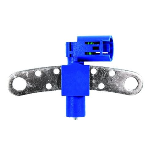
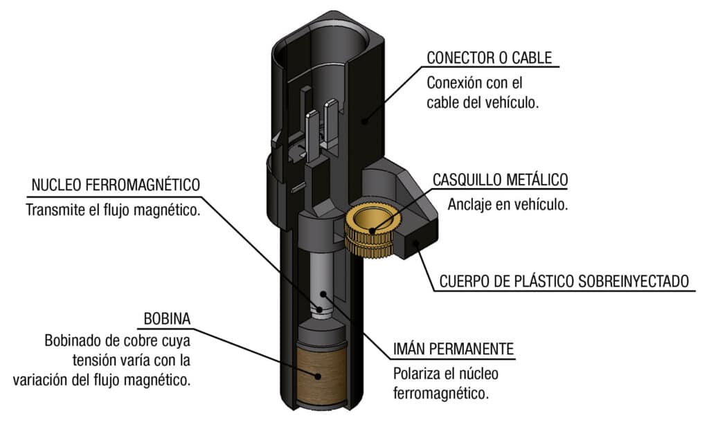
1.- Inductive Impulse Sensors
The sensor consists of a pickup coil, a magnetic core and a permanent magnet and is mounted in front of a gear wheel. As the teeth of the gear wheel (or other target features) pass by the face of the magnet, the amount of magnetic flux passing through the magnet and consequently the coil varies. When the gear tooth is close to the sensor, the flux is at a maximum. When the tooth is further away, the flux drops off. The moving target results in a time-varying flux that induces a proportional voltage in the coil which varies in function of the speed rotation and the distance to the gap in both frequency and amplitude. These variations cause the signal we receive as follows:

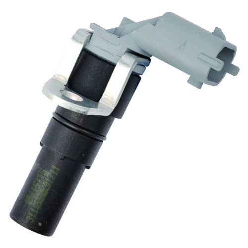
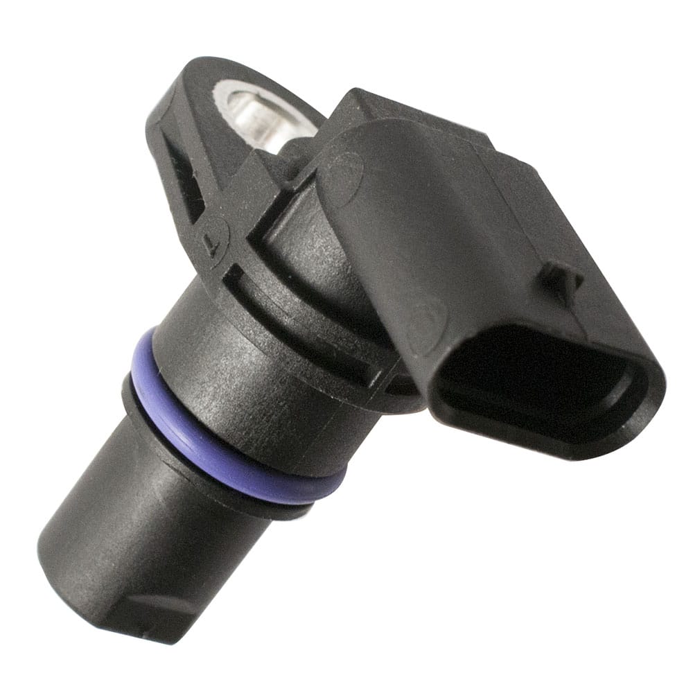
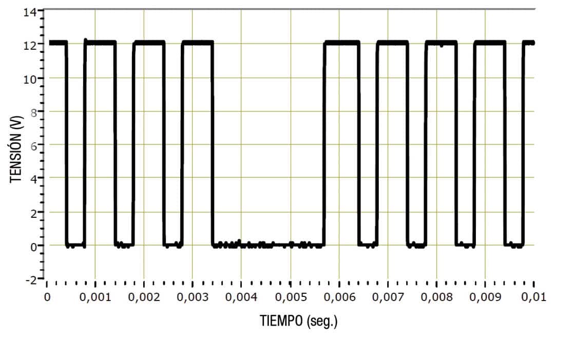
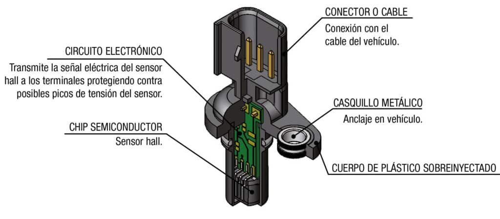
2.- Hall Effect Sensors
The sensor consists of a semiconductor sensor combined with an electronic circuit that protects the sensor from possible voltage peaks and a permanent magnet. The operating principle is based on the so-called Hall Effect, the production of a voltage difference (the Hall voltage) across an electrical conductor, transverse to an electric current in the conductor and a magnetic field perpendicular to the current. The response we get from the sensor is a U wave which is proportional to the variations detected by the sensor. These variations cause the signal we receive as follows:
Composition
Variable Reluctance Sensor
Hall Effect Sensor
Cause of failure
The outer body, connector and cables must be checked to ensure that they are in good condition.
Also check whether the sensor shows any cracks, dents or knocks that could have damaged it.
It should be noted that, as a general rule, a visual inspection is not sufficient to ensure that the part is working properly or not, but it helps to make an initial diagnosis.
Also check whether the sensor shows any cracks, dents or knocks that could have damaged it.
It should be noted that, as a general rule, a visual inspection is not sufficient to ensure that the part is working properly or not, but it helps to make an initial diagnosis.
- Cracks or breaks. Tensions provoked by mechanical stress
- Deformations and dents. Overheated sensor
- No signal. Failure of the wire due to friction or excessive vibration, short circuits, internal failure of the sensor due to mechanical or thermal stress.
SIGNS OF FAILURE OF SENSORS
- Not starting of the engine
- Power loss
- Not working of the speed gauge
- Warning light Engine Check is switched on
- Pulse failures of the injection
- Difficulties to start the engine
- Increase of fuel consumption
- Increase of emission levels
SENSOR MAINTENANCE
The specific values of the sensors must be checked each maintenance or every 25.000km. Replace the sensor whenever results are diagnosed which are not within the specified operating limits.
Mounting
Replace the gasket each time the sensor is changed. The gaskets do not perform their sealing function if these are used or worn.
